Packet Tracer |
您所在的位置:网站首页 › seafile服务器 客户端 › Packet Tracer |
Packet Tracer
|
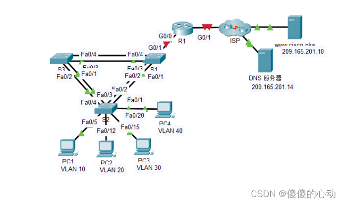
Packet Tracer - 综合技能练习 地址分配表 设备 接口 IP 地址 子网掩码 默认网关 R1 G0/0.10 172.31.10.1 255.255.255.224 不适用 G0/0.20 172.31.20.1 255.255.255.240 不适用 G0/0.30 172.31.30.1 255.255.255.128 不适用 G0/0.40 172.31.40.1 255.255.255.192 不适用 G0/1 已分配 DHCP 已分配 DHCP 不适用 PC1 NIC 已分配 DHCP 已分配 DHCP 已分配 DHCP PC2 NIC 已分配 DHCP 已分配 DHCP 已分配 DHCP PC3 NIC 已分配 DHCP 已分配 DHCP 已分配 DHCP PC4 NIC 已分配 DHCP 已分配 DHCP 已分配 DHCP VLAN 端口分配和 DHCP 信息 端口 VLAN 编号 - 名称 DHCP 池名称 网络 Fa0/5 – 0/9 VLAN 10 - 销售 VLAN_10 172.31.10.0/27 Fa0/10 – Fa0/14 VLAN 20 - 生产 VLAN_20 172.31.20.0/28 Fa0/15 – Fa0/19 VLAN 30 - 市场营销 VLAN_30 172.31.30.0/25 Fa0/20 - Fa0/24 VLAN 40 - HR VLAN_40 172.31.40.0/26 拓扑图
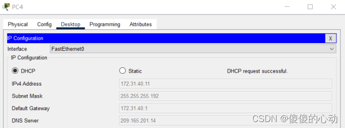
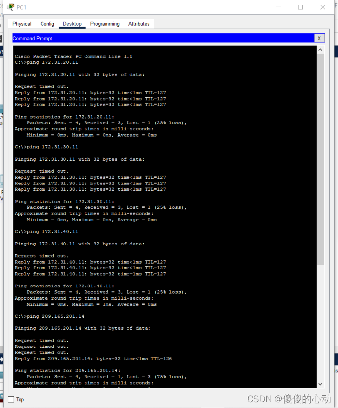
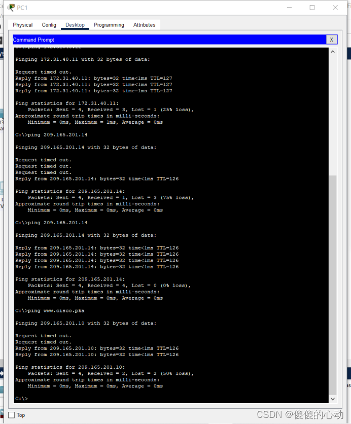
场景 在本总结练习中,您将配置 VLAN、中继、DHCP 服务器、DHCP 中继代理,并将路由器配置为 DHCP 客户端。 要求 使用上表中的信息,执行以下要求: · 在 S2 上创建 VLAN,并将 VLAN 分配到相应的端口。 名称区分大小写 vlan 10 name Sales vlan 20 name Production vlan 30 name Marketing vlan 40 name HR · 配置用于中继的 S2 端口。 interface range f0/1-4 switchport mode trunk · 将 S2 上的所有非中继端口配置为接入端口。 interface range f0/5-9 switchport mode access switchport access vlan 10 interface range f0/10-14 switchport mode access switchport access vlan 20 interface range f0/15-19 switchport mode access switchport access vlan 30 interface range f0/20-24 switchport mode access switchport access vlan 40 · 配置R1 在 VLAN 之间路由。 子接口名称应与 VLAN 编号对应。 interface g0/0 no shutdown interface g0/0.10 encapsulation dot1Q 10 ip address 172.31.10.1 255.255.255.224 interface g0/0.20 encapsulation dot1Q 20 ip address 172.31.20.1 255.255.255.240 interface g0/0.30 encapsulation dot1Q 30 ip address 172.31.30.1 255.255.255.128 interface g0/0.40 encapsulation dot1Q 40 ip address 172.31.40.1 255.255.255.192 · 配置 R1 作为连接到 S2 的 VLAN 的 DHCP 服务器。 - 为每个 VLAN 创建 DHCP 池。 名称区分大小写。 - 为每个池分配相应的地址。 - 配置 DHCP 以提供默认网关地址 - 为每个池配置 DNS 服务器 209.165.201.14。 - 防止各池中的前 10 个地址分配给终端设备。 ip dhcp pool VLAN_10 network 172.31.10.0 255.255.255.224 default-router 172.31.10.1 dns-server 209.165.201.14 exit ip dhcp pool VLAN_20 network 172.31.20.0 255.255.255.240 default-router 172.31.20.1 dns-server 209.165.201.14 exit ip dhcp pool VLAN_30 network 172.31.30.0 255.255.255.128 default-router 172.31.30.1 dns-server 209.165.201.14 exit ip dhcp pool VLAN_40 network 172.31.40.0 255.255.255.192 default-router 172.31.40.1 dns-server 209.165.201.14 exit ip dhcp excluded-address 172.31.10.1 172.31.10.10 ip dhcp excluded-address 172.31.20.1 172.31.20.10 ip dhcp excluded-address 172.31.30.1 172.31.30.10 ip dhcp excluded-address 172.31.40.1 172.31.40.10 · 验证各 PC 是否具有来自正确 DHCP 池的已分配地址。 注:分配 DHCP 地址可能需要一段时间。 点击加快转发时间加速进程。 · 将 R1 配置为 DHCP 客户端,使其能从 ISP 网络接收 IP 地址。 interface g0/1 ip address dhcp no shutdown · 验证所有设备现在是否可以互相 ping 并可 ping www.cisco.pka。 【实验过程】 //S2 S2>enable S2#conf t Enter configuration commands, one per line. End with CNTL/Z. S2(config)#vlan 10 S2(config-vlan)#name Sales S2(config-vlan)#vlan 20 S2(config-vlan)#name Production S2(config-vlan)#vlan 30 S2(config-vlan)#name Marketing S2(config-vlan)#vlan 40 S2(config-vlan)#name HR S2(config-vlan)#exit S2(config)#interface range f0/5-9 S2(config-if-range)#switchport mode access S2(config-if-range)#switchport access vlan 10 S2(config-if-range)#interface range f0/10-14 S2(config-if-range)#switchport mode access S2(config-if-range)#switchport access vlan 20 S2(config-if-range)#interface range f0/15-19 S2(config-if-range)#switchport mode access S2(config-if-range)#switchport access vlan 30 S2(config-if-range)#interface range f0/20-24 S2(config-if-range)#switchport mode access S2(config-if-range)#switchport access vlan 40 S2(config-if-range)#exit S2(config)#interface range f0/1-4 S2(config-if-range)#switchport mode trunk S2(config-if-range)#end S2#wr Building configuration... [OK] S2# //R1 R1>en R1#conf t Enter configuration commands, one per line. End with CNTL/Z. R1(config)#interface g0/0 R1(config-if)#no shutdown R1(config-if)# %LINK-5-CHANGED: Interface GigabitEthernet0/0, changed state to up R1(config-if)#interface g0/0.10 R1(config-subif)#encapsulation dot1Q 10 R1(config-subif)#ip address 172.31.10.1 255.255.255.224 R1(config-subif)#interface g0/0.20 R1(config-subif)#encapsulation dot1Q 20 R1(config-subif)#ip address 172.31.20.1 255.255.255.240 R1(config-subif)#interface g0/0.30 R1(config-subif)#encapsulation dot1Q 30 R1(config-subif)#ip address 172.31.30.1 255.255.255.128 R1(config-subif)#interface g0/0.40 R1(config-subif)#encapsulation dot1Q 40 R1(config-subif)#ip address 172.31.40.1 255.255.255.192 R1(config-subif)#exit R1(config)#ip dhcp pool VLAN_10 R1(dhcp-config)#network 172.31.10.0 255.255.255.224 R1(dhcp-config)#default-router 172.31.10.1 R1(dhcp-config)#dns-server 209.165.201.14 R1(dhcp-config)#exit R1(config)#ip dhcp pool VLAN_20 R1(dhcp-config)#network 172.31.20.0 255.255.255.240 R1(dhcp-config)#default-router 172.31.20.1 R1(dhcp-config)#dns-server 209.165.201.14 R1(dhcp-config)#exit R1(config)#ip dhcp pool VLAN_30 R1(dhcp-config)#network 172.31.30.0 255.255.255.128 R1(dhcp-config)#default-router 172.31.30.1 R1(dhcp-config)#dns-server 209.165.201.14 R1(dhcp-config)#exit R1(config)#ip dhcp pool VLAN_40 R1(dhcp-config)#network 172.31.40.0 255.255.255.192 R1(dhcp-config)#default-router 172.31.40.1 R1(dhcp-config)#dns-server 209.165.201.14 R1(dhcp-config)#exit R1(config)#ip dhcp excluded-address 172.31.10.1 172.31.10.10 R1(config)#ip dhcp excluded-address 172.31.20.1 172.31.20.10 R1(config)#ip dhcp excluded-address 172.31.30.1 172.31.30.10 R1(config)#ip dhcp excluded-address 172.31.40.1 172.31.40.10 R1(config)#interface g0/1 R1(config-if)#ip address dhcp R1(config-if)#no shutdown R1(config-if)#exit R1(config)#end R1# %SYS-5-CONFIG_I: Configured from console by console R1#wr Building configuration... [OK] R1# //PC1~PC4
【实验脚本】 //S2 enable conf t vlan 10 name Sales vlan 20 name Production vlan 30 name Marketing vlan 40 name HR exit interface range f0/5-9 switchport mode access switchport access vlan 10 interface range f0/10-14 switchport mode access switchport access vlan 20 interface range f0/15-19 switchport mode access switchport access vlan 30 interface range f0/20-24 switchport mode access switchport access vlan 40 exit interface range f0/1-4 switchport mode trunk end wr //R1 en conf t interface g0/0 no shutdown interface g0/0.10 encapsulation dot1Q 10 ip address 172.31.10.1 255.255.255.224 interface g0/0.20 encapsulation dot1Q 20 ip address 172.31.20.1 255.255.255.240 interface g0/0.30 encapsulation dot1Q 30 ip address 172.31.30.1 255.255.255.128 interface g0/0.40 encapsulation dot1Q 40 ip address 172.31.40.1 255.255.255.192 exit ip dhcp pool VLAN_10 network 172.31.10.0 255.255.255.224 default-router 172.31.10.1 dns-server 209.165.201.14 exit ip dhcp pool VLAN_20 network 172.31.20.0 255.255.255.240 default-router 172.31.20.1 dns-server 209.165.201.14 exit ip dhcp pool VLAN_30 network 172.31.30.0 255.255.255.128 default-router 172.31.30.1 dns-server 209.165.201.14 exit ip dhcp pool VLAN_40 network 172.31.40.0 255.255.255.192 default-router 172.31.40.1 dns-server 209.165.201.14 exit ip dhcp excluded-address 172.31.10.1 172.31.10.10 ip dhcp excluded-address 172.31.20.1 172.31.20.10 ip dhcp excluded-address 172.31.30.1 172.31.30.10 ip dhcp excluded-address 172.31.40.1 172.31.40.10 interface g0/1 ip address dhcp no shutdown exit end wr【实验验证】
【实验链接】 链接:https://pan.baidu.com/s/1ioK9SIHmnPo5_z0bTWsSVg?pwd=8312 提取码:8312 --来自百度网盘超级会员V3的分享 【实验知识点】 以下是实验涉及的知识点的详细罗列: VLAN(虚拟局域网):在网络设备上创建虚拟局域网,并将每个VLAN分配给相应的端口。中继(Trunk)端口:在交换机上配置用于连接不同VLAN的中继端口,以允许VLAN之间的通信。接入(Access)端口:将交换机上的非中继端口配置为接入端口,使其只属于指定的VLAN。802.1Q封装:在路由器接口上配置子接口,并使用802.1Q封装来将数据帧标记为特定的VLAN。IP地址和子网掩码:为每个子接口分配IP地址和相应的子网掩码,以使路由器能够在不同的VLAN之间进行路由。DHCP服务器和池:为每个VLAN配置DHCP服务器,并为每个池分配相应的网络地址范围。默认网关:为每个VLAN的DHCP池配置默认网关地址,使客户端能够访问其他网络。DNS服务器:为每个DHCP池配置DNS服务器地址,以提供域名解析服务。排除地址:为防止地址冲突或保留特定地址,配置排除地址范围,确保不将这些地址分配给终端设备。DHCP客户端:将路由器配置为DHCP客户端,以从ISP网络接收动态分配的IP地址。验证连通性:使用ping命令验证设备之间的连通性,确保各设备能够相互通信。实验脚本编写:根据实验要求,编写适当的命令脚本,以便快速配置设备。
请注意,上述知识点涉及到网络设备的配置和管理,以及基本的网络连接和通信概念。熟悉这些知识点对于进行网络配置和故障排除非常重要。 在实验中,每个错误都是一次宝贵的教训,坚持不懈,你将迎来突破的曙光。 |


【本文地址】
今日新闻 |
推荐新闻 |